PEM electrolysers
Published on 6 March 2022
Polymer Electrolyte Membrane (PEM) is one of the water electrolysis technologies to split water molecules into hydrogen and oxygen. Its name comes from the use of a gas-tight solid polymer-based membrane as electrolyte, the ion transport material between electrodes.
The PEM acronym is also sometimes referring to Proton Exchange Membrane, another accurate description of the technology.
Technology maturity
Development of PEM electrolysers resulted from research at General Electric on membranes for fuel cells during the 1960s. In theory, such an electrolyser or fuel cell can be operated in both modes: splitting water into hydrogen (electrolyser) or generating electricity from hydrogen (fuel cell).
Although a less mature technology than alkaline electrolysers, PEM electrolysers are commercially available. They have a similar efficiency to alkaline electrolysers but a significantly higher current density because H+ or more mobile than OH- within their respective electrolytes. While current density is restricted to 0.2-0.4 A/cm2 for alkaline electrolyser, it is within the 0.6-2.0 A/cm2 range with PEM electrolyser, meaning that a PEM electrolyser can be 5 times smaller while producing the same amount of hydrogen.
In addition to higher current density, PEM electrolysers can also operate at higher pressure (up to 200 bar) but still low temperature (50-80°C). Higher operating pressure means less energy consumption for compression at a later stage, improving the overall system efficiency.
PEM electrolysers produce hydrogen with a purity of 99.99+% without the need of additional purification equipment.
Electrolyser responsiveness
The difference in electrolyte state between alkaline and PEM electrolysers implies a large difference in inertia of the ionic transport. The liquid electrolyte within alkaline electrolysers is slow to response to any change in power supply. On the other hand, proton transport through a Nafion membrane is quick to respond to any in power fluctuation.
PEM electrolysers are therefore more relevant for direct coupling with renewable energy sources that are inherently variable in nature. By comparison, an alkaline electrolyser would require a storage device (battery, pumped hydro,…) to absorb power fluctuations, which is an additional source of losses.
Electrochemical reactions
In PEM electrolysers, de-ionised water is supplied to and split on the anode side through reaction
2 H2O ⇋ 4 H+ + O2 + 4 e-
Protons H+ are transported through the electrolytic membrane towards the cathode where hydrogen is produced by recombining them
2 H+ + 2 e- ⇋ H2
Being based on transport of H+ (rather than OH- for alkaline electrolysers) means that PEM electrolyser operate within an acidic environment. Accordingly, PEM electrolysers require noble catalysts, such as platinum and iridium for the electrodes.
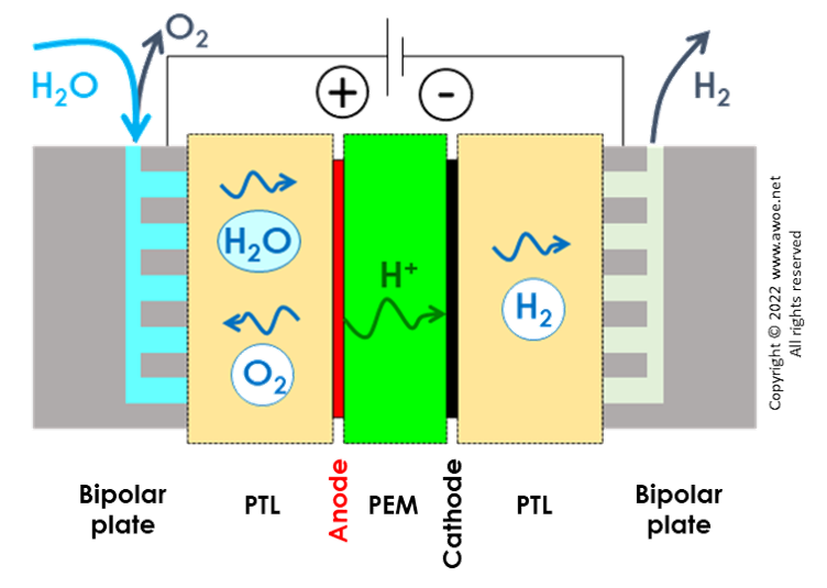
Schematics of a PEM electrolyser
Structure of a PEM electrolyser
The typical structure of a PEM electrolyser is a stacking of membrane electrode assemblies (MEAs) with intermediate layers that act as interconnector and gas collector. The individual cells are connected in series to create a system with significant voltage. At each end, current collectors made of aluminium or copper act as electric interface with the electrolyser surroundings.
An MEA is an assembly of a polymer electrolyte membrane with an oxygen electrode layer on the one side and a hydrogen electrode layer on the other side.
The porous transport layers (PTLs) are typically 280 micron thick, made of carbon paper on the cathode side and sintered titanium foam or felt on the anode side.
The interconnectors or bipolar plates ensure the electric connection of individual cells. They are made of titanium and shaped with channelling structures for water and gas transport. Some alternative designs use a titanium mesh to provide both the electric connectivity and some internal space fluid flow.
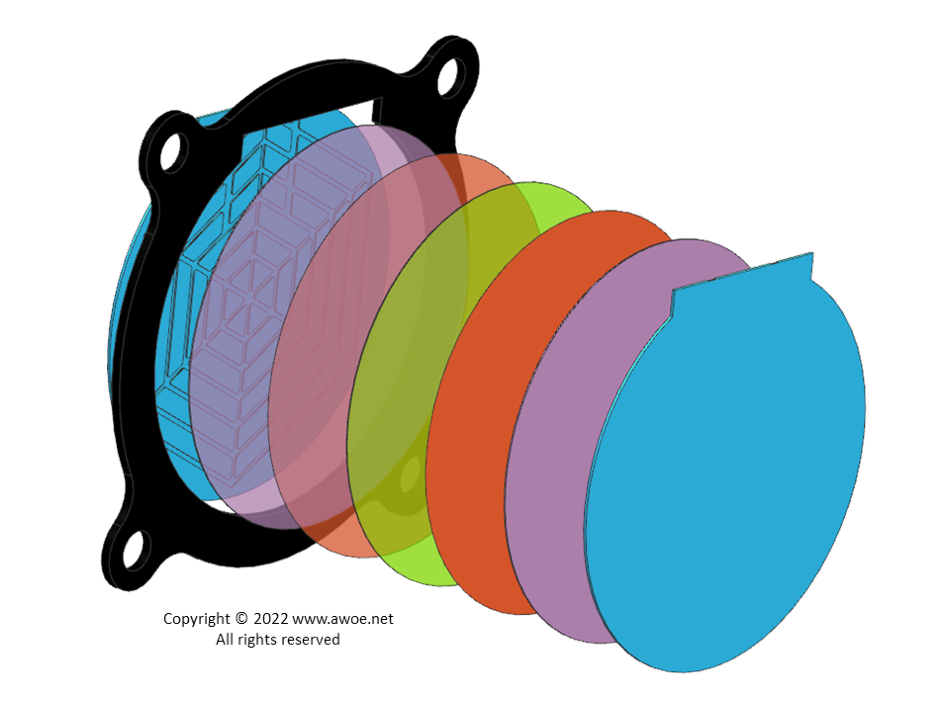
Exploded view of a PEM electrolyser
The frame surrounding the PEM cells is made of moulded plastic, optionally with steel reinforcement for pressurised electrolysers. Seals are made of nitrile, silicone rubber or FKM O-rings.
Finally, thick end plates and bolts ensure mechanical integrity by compressing the layers. Flat springs are added to the assembly to even distribute the compression, avoiding any local leakage.
Membrane
The solid membrane in PEM electrolyser is a perfluorosulfonic acid (PFSA) membrane. The most commonly used material is Nafion from DuPont, a copolymer of perfluorovinyl ether groups terminated with sulfonate groups into a tetrafluoroethylene structure. Once the copolymer is produced, it is treated first with a base, then an acid to convert the sulfonate groups into sulfonic acid. Being an acid allows it to conduct protons, which is labelled as having ionic properties. Nafion is very successful thanks to its good thermal and mechanical stability.
Within PEM electrolysers, Nafion membranes with a thickness of 60 to 200 microns are used. The membrane is the critical component that limits the lifetime of PEM electrolysers as it is more difficult to replace than the liquid electrolyte of alkaline electrolysers.
Electrodes
On both sides of the membrane, thin electrodes of about 10 μm thickness are directly bonded to the surface.
The anode of a PEM electrolyser works under very acidic and highly oxidising conditions, limiting the choice of possible material. The only known material providing both high electrode activity and material stability is iridium oxide (IrO2).
The requirement for iridium is a problem because it is a relatively rare material, mainly collected as a by-product of platinum production. Consequently, a significant portion of PEM research is targeted towards minimising the amount of used iridium through minimum loadings and shape optimisation of catalyst layers. High performance has been demonstrated with laboratory cells using as low a loading as 0.1 mg/cm2 but commercial loadings remain in the range of 1 to 3 mg/cm2.
The thin iridium coating is generally applied to a core of titanium or platinum-coated titanium, which are cheaper and more readily available materials than iridium but certainly not to the point of steel or aluminium.
The cathode operates within an acidic but reducing environment, reducing the demand on materials. Cathodes are commonly made of platinum black or of platinum layers on a carbon core. Platinum loading is within the range of 0.2 to 1 mg/cm2.
Platinum group metals or titanium cores coated with platinum group metals are also used for the interconnects (or bipolar plates), so that such materials are used in large quantities in a PEM electrolyser.
Efficiency
The minimum voltage for water splitting into hydrogen and oxygen is 1.23 V (see Electrolysis General). However, industrial electrolysers use a higher voltage to maximise productivity. The ratio between the ideal and the practical voltages defines the efficiency of an individual cell:
Eff = 1.23V / Ecell
Industrial applications operate at a cell voltage of 1.5 to 2 V, leading to a cell efficiency of 62 to 82%. Yet, an industrial electrolyser also includes numerous utilities (pumps, transformers, control electronics,…) and operation implies some faradaic losses (unwanted side reactions within the cell). When operating an electrolyser around 30 bar to produce 99.999% pure hydrogen, such losses account for 10-20%, so that the electrolyser efficiency is in the range of 50 to 70%.
Water treatment and usage
Water de-ionisation is required before feeding to the anode to avoid mineral deposition and non-desired electrochemical reactions in the cells. When water is pumped into the stack, it flows through an ion exchange resin cartridge to ensure low water conductivity (< 0.1 μS/cm) to avoid quick system degradation.
The anodic side also includes a heat exchanger to control the system temperature, generally between 60 °C and 80 °C. The cathodic side does not include a cooling circuit because there is a net transport of water from the anode to the cathode during operation due to the electro-osmotic drag. Controlling temperature on the anodic side therefore indirectly controls temperature on the cathodic side and the cathodic side includes a water drainage outlet.
Because the cathodic outlet flows a mixture of hydrogen and water, it is cooled down to near ambient conditions for easy separation of liquid water from gaseous hydrogen. The liquid water is then drained back to the anode.
The hydrogen flow is purified in 2 consecutive steps:
- a catalytic de-oxo purification to reduce the oxygen content below 5 ppm
- an adsorptive dryer to reduce water content below 5 ppm
Operating conditions
When operating a PEM electrolyser at higher pressure, it does not necessarily mean that all circuits are high-pressure. The oxygen side is generally kept near ambient pressure to simplify the system design and limit oxygen permeation towards the hydrogen side. This has limited consequences as long as produced oxygen is not used by directly vented to the atmosphere. Only the hydrogen side will experience some significant pressure.
Today, commercial PEM electrolysers have a lifetime of 40,000 to 60,000 hours. The membrane electrode assemblies and the anodic transport layers are the limiting parts. Their overhaul allows to keep the complete structure operative for a longer period.