Water electrolysis
Published on 3 January 2022
Water electrolysis is the splitting of water molecule H2O into gaseous hydrogen H2 and gaseous oxygen O2 using a direct current (DC). The purpose is to create relatively rare but energy-dense hydrogen H2 out of abundant water H2O, pure oxygen generally being a by-product.
The water molecule is decomposed into a pair of ions at one electrode, the nature of the decomposition depending on the electrolyser type. One type of ion reacts at the water splitting electrode, while the other type is transported to the second electrode through an electrolyte with the help of the electric field. At the cathode, hydrogen H2 is produced and electrons e- provided by an external source are consumed. At the anode, oxygen O2 and electrons e- are produced. During operation, a direct current continuously flows but with different charge carriers in and out of the electrolytic cell: the charge carriers are electrons out of the cell, while they are ions within the cell.
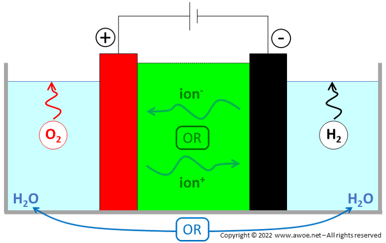
Schematics of water electrolysis
Beyond the ion transport function, the electrolyte also acts as an electric insulation between electrodes and as a gas separator to avoid mixing between H2 and O2 just after water splitting. The multi-function nature of the electrolyte explains why only a few materials are appropriate.
Technology evolution
Water electrolysis is not a recent discovery but still a domain with active technological development. It is historically the first known method to produce pure hydrogen but is, however, not a mainstream technology today because H2 production from fossil fuels is cheaper. Yet, environmental concerns and the growing availability of renewable electricity are likely to increase the share of water electrolysis in the hydrogen production landscape in the near future.
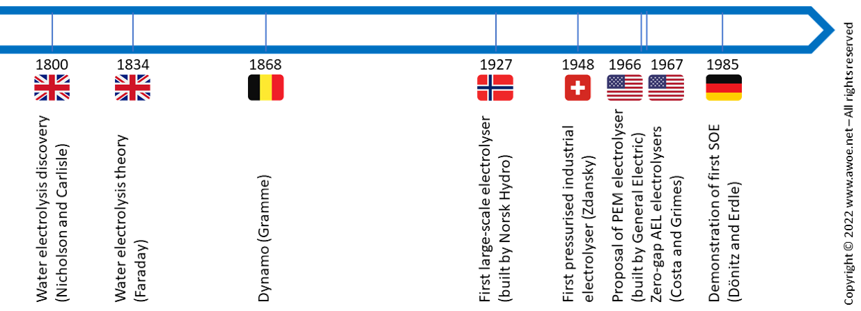
Timeline of water electrolysis development
Water electrolysis was discovered in the early days of the nineteenth century and understood as soon as 1834. With the invention of Gramme’s dynamo in 1868, pure hydrogen could be easily produced at laboratory scale. During the twentieth century, electrolyser evolved towards large-scale industrial units (1927) with increasing productivity (1948, 1967). Alternatives to the traditional alkaline electrolysers became available with progress in materials for separators with the aim of improving compactness (PEM, 1966) and efficiency (SOE, 1985).
There are 3 main types of electrolysers:
- Low-temperature electrolysers with a liquid electrolyte: Alkaline electrolysers (AEL)
- Low-temperature electrolysers with a solid electrolyte: Polymer Electrolyte Membrane electrolysers (PEM)
- High-temperature electrolysers with a solid electrolyte: Solid Oxide electrolysers (SOE)
Note that the last 2 types are theoretically reversible installations that could be used either as electrolyser (making H2 from electricity) or fuel cell (making electricity from H2).
Being the original concept developed from more than 2 centuries, alkaline water electrolysis is the most developed, mature, and commercially available technology since decades. Those electrolysers are reliable, safe and constitute the go-to electrolysis technology at commercial level worldwide. Their main drawback is weight and size when compared to the other types for the same H2 output. Polymer Electrolyte Membrane electrolysers are commercially available, a lot more compact that alkaline electrolysers and better suited for intermittent and part-load use. Nevertheless, there are today still more expensive and have a shorter lifetime. Beyond compactness, Solid Oxide Electrolysers (SOE) should also bring benefits in efficiency but are still in a development phase.
Current density
By concept, the amount of produced hydrogen depends on the electron flow through the electrical circuit in-between electrodes. Accordingly, the amount of produced H2 is directly related to the current density (current per electrode area, in A/cm2) when comparing systems of the same size.
A higher current density is advantageous to produce more hydrogen with a given electrolyser. But being integrated within an electric circuit, a higher current density also means a higher voltage due to the circuit resistance, hence an electric consumption that grows quicker than the hydrogen production (P = V.I = R.I2).
There is an economic trade-off between the electrolyser size and the electric consumption to minimise the cost of H2 production:
- A larger, low-current electrolyser has a large initial investment (CAPEX) but low operating costs (OPEX)
- A smaller, high-current electrolyser requires less initial investment (CAPEX) but has high operating costs (OPEX)
Operating voltage
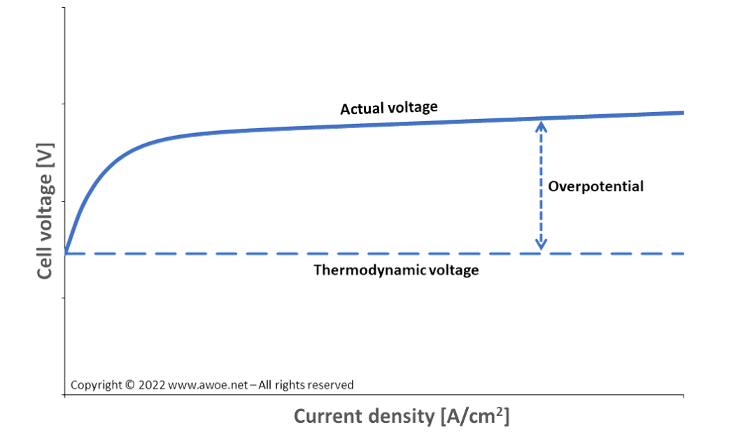
The thermodynamic voltage required to split a water molecule at ambient conditions (1 atm, 298 K) is 1.23 V. Yet, this is the voltage for a negligible current density and therefore not the appropriate voltage for an industrial application.
When flowing a significant current, system losses appear dissipating some of the electric energy into heat. The consequences are:
- The need to supply more energy than thermodynamically expected to drive the reaction
- A cooling requirement for the electrolytic cells of low-temperature electrolysers
The required extra energy is generally expressed in terms of overpotential, i.e. the extra voltage above 1.23 V for the electrolytic cell to produce hydrogen. The overpotential depends both on the cell design (sizing, layout, material selection, …) and on the operating conditions (grows with current density, varies with temperature).
Schematics of overpotential in electrolytic cells
There are 3 main categories of overpotential:
- Activation overpotential, related to the electron transfer between the electrolyte and each electrode (highly dependent on the selection of electrode and electrolyte materials, but also on geometry – porous electrodes vs flat/solid electrodes). For water electrolysis the anodic overvoltage is significantly larger than the cathodic one because the kinetics of the O2 reaction is much slower than that of H2 reaction
- Resistance overpotential, related to the electron transfer between electrodes (the classic electric circuit resistance)
- Concentration overpotential, related to the ion transfer within the electrolyte mainly through concentration (lower ion concentration at the electrodes than in the bulk of the electrolyte becomes a limiting factor)
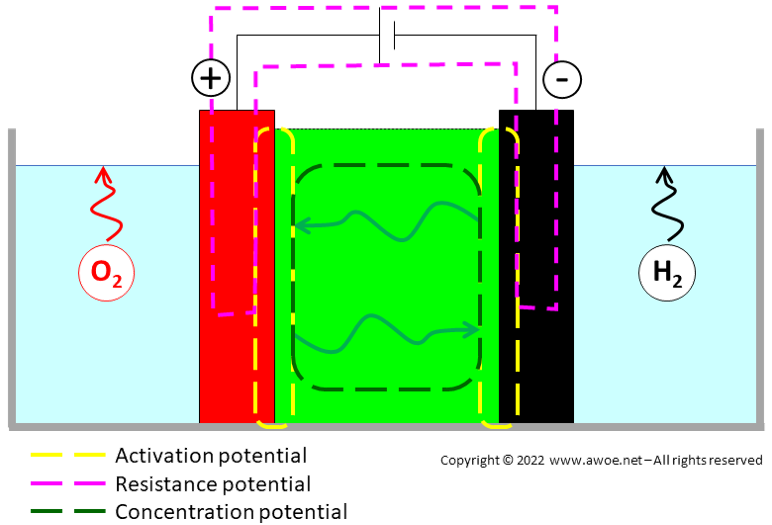
Location of overpotentials in electrolytic cells
Activation overpotential generally has a very steep dependence on current density at low current and then levels off, while resistance overpotential is more linear. In any case, the sum of overpotentials remains lower than the thermodynamic voltage and the overall electrolysis voltage dependence on current density has the general shape displayed in the schematics above.
System pressure
At atmospheric pressure, the total energy ΔH required to split liquid water is almost independent of temperature (range 0-100°C). Yet, required electrolytic cell voltage Ecell decreases with increasing temperature T because Ecell relates to Gibbs energy ΔG:
Ecell = ΔG/nF = (ΔH – T ΔS)/nF
Accordingly, low-temperature electrolysers run at the highest possible temperature supported by the weakest material (typically 80-90°C) to minimise electric consumption both for the electrolysis itself and for cell cooling (less coolant pumping).
By pressurising the system, liquid water splitting range can theoretically be expanded up to 230°C. Yet, material constraints currently limit effective operating temperature to 100-130°C. Furthermore, pressurising slightly increases the required cell voltage (increase by about 0.2V when shifting from 1 to 700 bar). Therefore, operating at above-atmospheric pressure is not generally done to gain efficiency on the water electrolysis step but to avoid or restrict the amount of hydrogen compression in-between electrolysis and storage (generally at 350 or 700 bar).
At high electric current or high operating pressure, some mass transport across the separator occurs because gas solubility in the electrolyte is not strictly zero. Transport of electrolyte then implies fractional transport of gas (H2 or O2). Flow of H2 and O2 across the separator is proportional to their diffusion coefficient and reduces system efficiency.
Electrolytic cell versus electrolyser
Just like a battery, an electrolyser does not operate at the electrolytic cell voltage but at much higher voltages of a few hundred volts. Individual cells are assembled in series within stacks to reach the desired voltage. The stacks can then be assembled in parallel to absorb more current/power.
In modern designs, an electrolysis cell is a galvanic chain of planar geometry containing 2 metallic electrodes placed face-to-face and clamping a thin electrolytic layer. The electrolytic layer can be ions dissolved in a liquid polar solvent (AEL), an ion-conduction polymer (PEM) or an oxygen ion-conducting ceramic (SOE). The stack is built by accumulating electrolytic cells and clamping them to avoid any leakage.
Lifetime
Any electrolyser is expected to operate properly over a period of multiple years, i.e. 45.000 h (~5 years) or more.
The older designs of alkaline electrolysers demonstrated lifetime of more than 100.000 h and up to 15 years. Newer systems operating at higher pressure or temperature have higher productivity and/or efficiency but have a lifetime reduced to 50.000 to 70.000 h (6-8 years under continuous operation).
PEM electrolysers should have a similar lifetime as alkaline electrolysers, but most of commercial products have a lifetime of less than 40.000 h (~5 years of continuous operation). As of today, there is still a lack of detailed understanding of the degradation mechanism, which impedes further progress.
Solid oxide electrolysers have currently a lifetime of a few thousand hours with an efficiency degradation of about 1% per 100-h of operation. Yet, progress in materials and thermal management leads to continuous improvements.