Life Cycle Analysis of hydrogen production with alkaline electrolysers
Published on 10 January 2022
Hydrogen is considered a clean fuel or a clean energy carrier as it is carbon-free and can be generated from water and renewable electricity. However, even if made entirely from renewable resources and therefore labelled green hydrogen, it still has an environmental impact through resources required to build the renewable electricity harvester and the electricity-to-hydrogen converter, namely an electrolyser.
There are 3 types of electrolysers: alkaline, polymer electrolyte membrane and solid oxide. Alkaline electrolysers is the most mature technology and the most widespread in industrial applications. It has notably already been implemented in hydrogen fuel stations for vehicle, directly producing hydrogen on-demand at dispensing point.
The environmental impact of green hydrogen is at least the sum of the environmental impact of renewable electricity and of that of electricity conversion into hydrogen. Wind turbines are a source of renewable electricity with a low environmental impact on a complete Life Cycle, making them a favoured solution to produce green hydrogen. To complement the analysis on wind turbines, a Life Cycle Analysis on alkaline electrolysers is necessary.
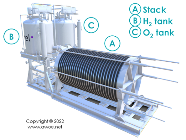
Part inventory of an alkaline electrolysis plant
Alkaline water electrolysis splits water molecule H2O into hydrogen H2 and oxygen O2 consuming electricity. However, it does not run on tap water to avoid mineral deposition and uncontrolled electrochemical reactions. Instead, an alkaline electrolyte made of a mixture of purified water and a strong alkali additive (generally KOH at about 25%mas) is the ion carrier. The first element in an alkaline electrolysis plant is therefore a water purifier, which has an energetic cost.
The water demand for H2 production is about 1 l/Nm3 H2 (1 m3 at 1 atm, 20°C) or 8.3 l/kg H2 once purified, requiring 9-10 l of raw water.
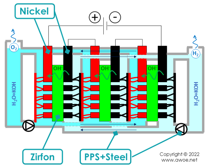
Pumps made of material resistant to the corrosion from a strongly alkaline mixture (some type of polymer) circulate the electrolyte into the stack of electrolytic cells. The cells themselves are made of a frame, electrodes, electric interconnections and a diaphragm/separator. A gasket seats in-between cells in the stack to prevent leakage.
Once produced, hydrogen and oxygen are each routed towards a dryer and then a tank. At electrolyser outlet, hydrogen is at a pressure of 5 to 30 bar. Further compressor might be required for storage or dispensing but this is out of the scope of the present alkaline electrolyser analysis.
Layout of an alkaline electrolyser
The electrolytic cells use low-voltage direct current (a few hundred volts) while the electric grid (or a directly coupled wind turbine) provides high-voltage alternate current (at least dozens of kilovolts). Accordingly, the electrolyser plant includes a transformer and a rectifier with power electronics.
Life Cycle Analysis
The environmental impact of the electrolyser results from the extraction of materials for each sub-element listed above, the manufacturing of sub-elements from raw materials, as well as the environmental burden inherited from the electricity production (renewable or not).
The key materials in an alkaline electrolyser are:
- Steel for all the tanks, pipes, cell frame reinforcement and containers
- Nickel for the electrodes
- Zirfon for the diaphragm
- A strong alkali, generally potassium hydroxide (KOH)
- A corrosion-resistant polymer, for example polyphenylene sulfide, as main component for the frame and/or for the pump
- Aluminium and copper in the power electronics
- Polytetrafluorethylene (PTFE) for the gasket in-between cells
Key materials in the stack of an alkaline electrolyser
Due to the relative quantities and the environmental impact of raw material extraction, steel and nickel are the most influent materials. The relative proportion of steel and nickel within the electrolyser stack varies based on its design, but the use of steel for piping, tanks and electrolyser container makes it the most significant component on the overall plant.
Depending on how and where the installation is implemented, concrete for foundation might also become a significant contributor.
Electrolyser stack
The impact of the electrolyser stack, i.e. the core electricity to hydrogen converter, depends on design, size (there is an economy of scale for MW units compare to kW units) and mostly operating strategy. Most installation are designed for a life duration of 20 years. Within this timeframe, operating the electrolyser 2000 or 8000 hours per year makes a huge difference on the environmental impact as the absolute emissions for the foundations, the tanks, the piping or the container are identical whatever the amount of produced hydrogen. In the present analysis, data are presented for 8000h/y of operation assuming that there is some network management or energy storage to maintain renewable electricity supply (almost) all year round.
Long hours of operation per year come with more ageing of cells due to the corrosive effect of the alkaline electrolyte. To maintain high efficiency, the electrodes and the diaphragm have to be periodically replaced or refurbished. Over 20 years with 8000 h/y, 1 to 3 interventions on electrodes and diaphragm are planned on recent units. In such a case, the impact of raw materials, manufacturing and replacement work are accounted as operational emissions rather than construction emissions (see section Electrolyser plant). An intervention on electrodes and diaphragm is generally coupled with a flush of the electrolyte that also requires periodic renewal.
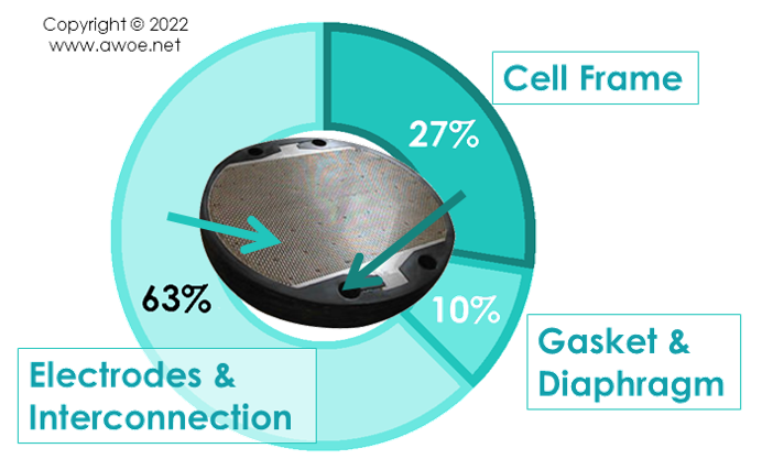
Split of environmental burden within an alkaline electrolyser stack
With these assumptions, the environmental impact of the stack construction is:
- 20-35% is the cell frame (polymer + steel)
- Almost 10% is gasket and diaphragm
- The rest being the electrodes and electrical interconnection
More than half the impact is the electrodes because of the materials and manufacturing methods selected to optimise the stack efficiency. Activated coatings on perforated or porous electrodes require labour/energy-intensive processes.
Electrolyser plant
Because of the low current density used in alkaline electrolysers, the cell stack is huge compared to the other pieces of equipment in the plant. Accordingly, the construction of the plant is largely dominated by the construction of the cells. When excluding the foundations, the relative weight of the stack on the environmental impact of the construction is about 90%, with power electronics as a distant second.
Beyond construction, the environmental impact of operation, excluding electricity supply, is also dominated by the electrolyser stack, mainly due to the periodic replacement of electrodes. The impact split over the complete life cycle is around:
- 70% during the construction phase
- 28% during the operation phase
- 2% at disassembly and disposal
Carbon footprint of the electrolyser plant
Still excluding electricity supply, the total carbon footprint of the electrolyser ranges from 43 to 287 gCO2,eq/kgH2 among published data . The lower end of the range relates to installations for which no electrode replacement is apparently accounted for, while higher numbers have multiple replacements over the 20-year lifetime. A narrower range of 86 to 138 gCO2,eq/kgH2 appears as a consensus on installations with a single mid-life electrode replacement, with equivalent emissions going down when the installation becomes bigger.
Efficiency and electric consumption
Although the carbon footprint range of the electrolyser plant might seem wide, it only has a secondary influence on the complete carbon footprint of electrolytic hydrogen because of the required amount of electricity.
The main reason for the large electric consumption is the energy required to split a water molecule: ~39.5 kWh/kgH2, about 1.2 times the energy content of the resulting H2 molecule. Additionally, alkaline electrolysers operate with an efficiency of 70-80% at the stack level but at an efficiency of 60-67% at the plant level. The result is a specific energy consumption of 59-66 kWh/kgH2 (about 1.75 to 2 times the energy content of the resulting H2 molecule).
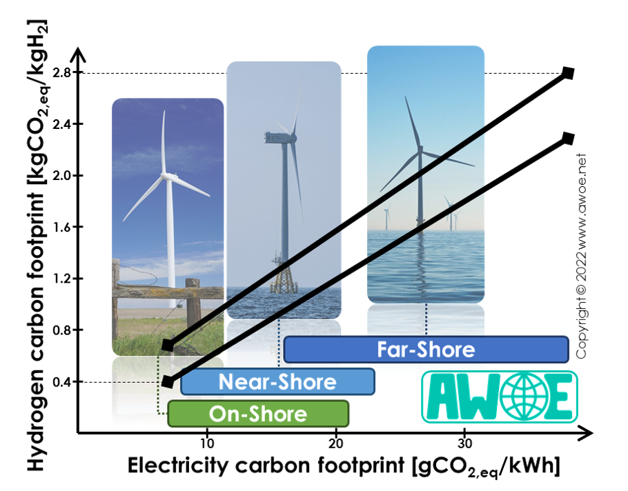
Carbon footprint of H2 based on wind turbine electricity
The carbon footprint of electricity generated by wind turbines is 7-38 gCO2,eq/kWh (see Life Cycle Analysis of wind turbines). As a consequence, the electricity supply for water electrolysis alone has a carbon footprint of 413-2508 gCO2,eq/kgH2, significantly more than the electrolyser carbon footprint, while wind turbines are among the cleanest source of renewable electricity.
Combined with the electrolyser impact, the total carbon footprint of hydrogen production is then 456-2795 gCO2,eq/kgH2, 90% of it relating to the electricity supply. For reference, the carbon footprint of the most common way of producing hydrogen, Steam Methane Reforming (SMR) is 12-15 kgCO2,eq/kgH2. Electrolysis hydrogen powered by wind turbines is therefore 80-97% cleaner than today's reference H2 production method.
Carbon footprint of green hydrogen derived from wind turbine electricity with an alkaline electrolyser