Hydrogen refuelling station
Published on 3 April 2022
Hydrogen refuelling stations differ from conventional liquid fuel stations by the level of control required during fuelling to maintain safety.
While liquid fuel is delivered just above ambient pressure by forcing fuel through the pressure losses of the dispenser, delivering hydrogen means manipulating gas at up to 900 bar, creating large mechanical and thermal stress within vehicle tanks. Besides, to remain competitive with conventional fuels, a similar refuelling time of 3-4 min is expected, which further amplifies stress due to the quick dynamics of constraint build-up.
To reach such an objective, refuelling is fully controlled by the station, selecting the flow rate, controlling gas temperature notably by cooling hydrogen (down to -40°C) and adapting to ambient conditions (mainly ambient temperature).
Hydrogen temperature
During refuelling, hydrogen flows from a high-pressure tank into the vehicle tank, only based on pressure difference, although with flow rate controlled by a valve.
Contrary to conventional liquid fuel refuelling, the user has no control on the fuelling flow rate because the hydrogen flow rate influences the temperature rise within the tank. This temperature must be kept below a critical value for safety reasons (international standard, notably SAE J2600 & J2601, restricts the average tank temperature to 85°C).
Temperature management during refuelling is specific to gas refuelling and more particularly to hydrogen because of its properties. Gas refuelling implies compressing the gas already present within the tank with the added gas from the high-pressure source. Such a compression increases temperature within the tank. Additionally, hydrogen has the specific property of heating up while expanding from high to low pressure (Joule-Thomson effect), so that the expansion across the valve controlling the flow rate also raises the gas temperature.
The necessity to keep the tank temperature below 85°C originates from safety concerns for high pressure tanks (350 or 700 bar). An excessive increase in tank temperature would lead to a weakening of the tank materials, reducing their capacity to withstand the gas pressure. Furthermore, while a tank is rated at 700 bar at 15°C, it can experience up to 875 bar under hotter environmental conditions.
Required control over tank temperature means that the flow rate delivered by the fuelling station will depend on ambient temperature and station cooling capacity. If ambient temperature is higher, flow rate will be reduced to limit the temperature rise within the tank. If the fuelling station is equipped with the most effective cooling system, it can deliver hydrogen down to -40°C, so that it can cope with higher ambient temperature before any significant derating in flow rate.
Hydrogen pressure
Most hydrogen vehicles are equipped with tanks rated either at 350 or 700 bars. These pressures are the levels required at 15°C to reach the nominal hydrogen mass within the tank. Such pressures are high to compensate for hydrogen very low density, so that an appropriate amount of hydrogen can be stored to deliver a reasonable vehicle range (H2 consumption for an up-to-date fuel cell car is about 1kg of hydrogen for 100 km, so that tanks of about 5 kg of hydrogen are common).
While tanks are rated at 350 or 700 bar, they can operate at higher pressure to cope with higher ambient temperature (protocol limits are -40°C to +50°C). A 700 bar tank can operate up to 875 bar under hot ambient conditions without any risk of failure, thereby also requiring the refuelling station to be able to deliver more than 700 bar on a hot day.
Fuelling being realised by flowing from a high-pressure source into a lower pressure tank, the fuelling station pressure therefore needs to reach much more than 700 bar. Because the flow-controlling valve, the hydrogen cooler and the dispenser are pressure losses between the source and the vehicle tank, delivering about 800 bar means having an even higher pressure source, generally in the range of 900-950 bar. Given the high energy consumption to reach such pressure levels, the refuelling station will work at the lowest practical value within this range.
Storing a large quantity of hydrogen at 900 bar would require large very-high-pressure-rated tanks and such tanks are very expensive. Beyond cost, there is also the hazard of storing large quantities of hydrogen at very high pressure and the potential large losses related to pressure control within a hot environment. Accordingly, most stations either have a local electrolyser (producing hydrogen when required) or use an intermediate pressure storage (generally between 200 and 250 bar, the standard for gas tanks on trailers), both connected to a compressor to reach up to 900 bar. Because compression increases gas temperature, the compressor is generally followed by a chiller to get hydrogen back to ambient temperature and to reduce the demand on the hydrogen cooler during dispensing.
Pressure ramp-up
SAE standard dictates that fuelling must be a linear increase in pressure within the vehicle tank, with flow rate controlled based on expected maximum temperature within the tank during the fuelling. The valve control is therefore based on the knowledge of fuelling evolution depending on ambient conditions, fuelling station capabilities and vehicle tank conditions. Such a knowledge comes from standard look-up tables or standard correlations defined in the SAE standard.
While using look-up tables, initial conditions entirely control the fuelling as the method does not require feedback from vehicle tank. The pressure ramp is defined to ensure never to exceed 85°C of tank temperature whatever the type of tank and vehicle. This method is therefore safe but conservative in most conditions, hence suboptimal in terms of fuelling duration.
With the correlations using feedback from vehicle (after an initial 30s stage based on look-up tables), the instantaneous flow rate can be adapted during the fuelling depending on vehicle characteristics to reach higher mass flow rate while keeping the maximum temperature within the safe range. The correlation method accelerates fuelling by adapting to specific vehicles. Depending on conditions, this can result in energy savings or overconsumption (about 6% in each direction).
In any case, the hydrogen flow rate can never exceed 60 g/s to avoid overheating the vehicle tank, so that filling a 5 kg tank from empty requires at least 1½ minute. In reality, the table-based fuelling protocol applied to a 700 bar tank at an ambient temperature of 20°C dictates an average pressure ramp rate (APRR) of 21.8 MPa/min and a final pressure of 74.5 MPa, so that the refuelling of an empty tank requires 3½ minutes.
Such a pressure ramping up approach means that the initial part of the fuelling creates most temperature increase because:
- The pressure in the vehicle tank is the lowest, leading to the highest expansion across the valve
- The gas already within the tank experiences the largest compression ratio of the complete refuelling cycle
Energy consumption
The simplest installation to deliver hydrogen at 900 bar to a control valve would be to only have a compressor pumping from an intermediate pressure storage. However, this requires the compressor use to be synchronised with hydrogen delivery and to size the compressor with maximum required flow rate. High flow rate and fast response both impose to oversize the compressor with respect to an alternative design with a buffer tank.
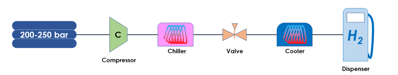
Hydrogen refuelling station layout without buffer tank
Accordingly, a practical fuel station always includes at least a buffer tank that delivers hydrogen to the dispenser through the control valve and cooler. This buffer tank is replenished by the compressor late in the refuelling event or after the refuelling event. From an energy consumption perspective, a full refuelling event includes delivering the hydrogen and then setting the high-pressure source back to its original status, i.e. compressing some hydrogen to 900-950 bar.
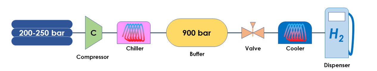
Hydrogen refuelling station layout with a buffer tank
During the refuelling event, energy consumption is mainly related to hydrogen cooling for vehicle tank temperature management. After the refuelling (or late in the refuelling if the buffer tank has a small capacity), the compressor delivers some very high pressure hydrogen to the buffer tank to keep it within the 900-950 bar range.
The hydrogen compression up to 900-950 bar represents about 50% of the total energy consumption, while the chiller consumes about 30% of total energy and the cooler on the dispenser side consumes about 20%.
Cascade installation
Compression of hydrogen to 900 bar being the largest share of energy consumption, shortening the use of a 900 bar source during refuelling is key to save energy. To do so, a cascade installation splits the buffer volume into multiple tanks with various pressure levels. The lowest pressure level is used at the beginning of refuelling before automatically switching to the intermediate pressure levels and only use the highest (900 bar) pressure level for the final stage.
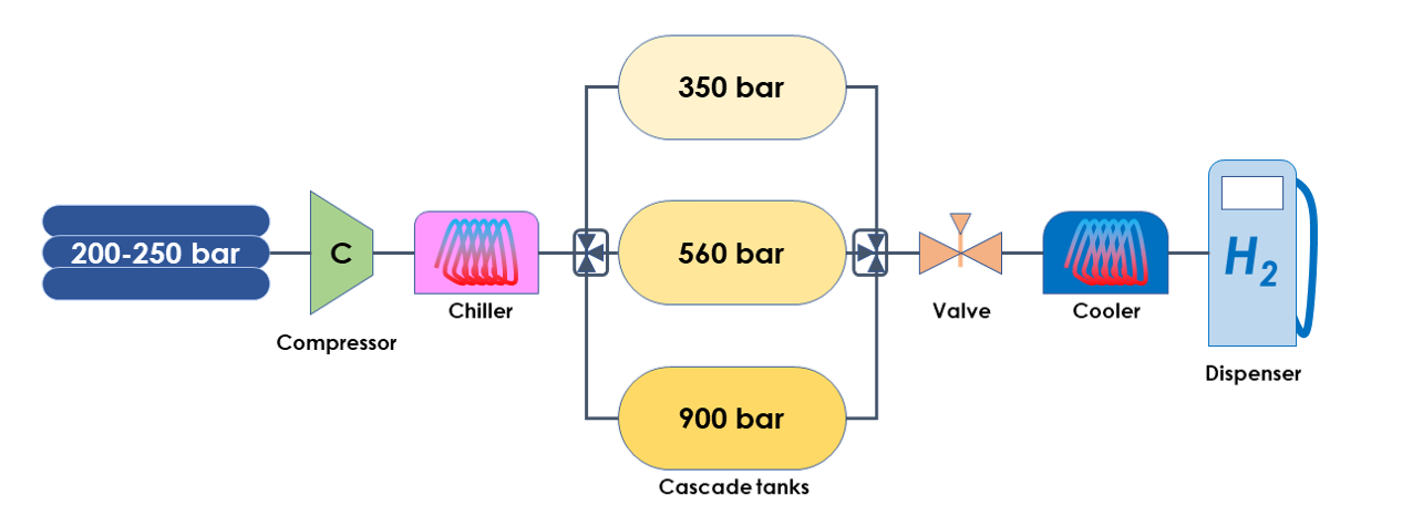
Hydrogen refuelling station layout with a cascade of buffer tanks
Multiple analyses of cascade installations have shown that a set of 3 buffer tanks with a geometric progression of pressure levels is the best approach to save energy. A low-pressure buffer tank stores hydrogen at about 350 bar. An intermediate-pressure buffer tank stores hydrogen at about 560 bar. And a high-pressure buffer tanks store hydrogen at about 900 bar. There is a spike in cooling requirements when switching between tanks as pressure ratio across the control valve jumps up. The split of pressure levels therefore also influences the sizing of the coolers and the related capital cost.
During refuelling, the vehicle tank is connected to the lowest level first until the pressure gap across the control valve reaches a certain limit, then switches to the intermediate level and only uses the highest level for the final part of the fuelling. The energy saving with this approach comes from
- The use of a lower pressure source for a large portion of the refuelling, leading to less compression work to bring these tanks back to their original pressure
- The reduced expansion across the control valve, reducing the gas heating (Joule-Thomson effect) and therefore reducing the energy consumption at the cooler
- The faster buffer tank refilling means a capacity for more vehicle refuelling within a given period, reducing the required compressor and dispenser count to deal with a vehicle fleet, limiting station auxiliary consumption
The total energy saving when going from a single buffer tank to three buffer tanks is about 1/3. There are still savings with more tanks but gains become small while extra costs are high. A 3-buffer-tank system is therefore generally viewed as the best trade-off. As an order of magnitude, refuelling 240 kWh of hydrogen into a vehicle tank consumes about 6 kWh, i.e. about 2.5% of the energy content.
Once refuelling is over, refilling each buffer tank can be done starting with the lowest or the highest pressure level. The order for refilling only has a modest effect on energy consumption (about 1% lower when starting from lowest) but starting from the highest has the benefit of allowing multiple consecutive refuelling events without much loss in capacity.
Note that, because the table-based refuelling protocol defines flow rate exclusively based on ambient conditions and station maximum capabilities (highest pressure, lowest cooling temperature), there is no difference in refuelling duration between a single-tank and a cascade installation. However, by depleting less the highest-pressure tank, the cascade installation is capable of more consecutive refuelling events.