Hydrogen compression
Published on 16 January 2022
Hydrogen is generally produced at low pressure (5 to 30 bar), conditions under which it occupies a huge volume per unit of weight: at 5 bar and 25°C, hydrogen occupies 2.48 m3/kg while air only occupies 0.17 m3/kg. Accordingly, storing or transporting hydrogen is always done at high pressure to save space. Most common storage pressures are either 350 bar or 700 bar, implying a compression pressure of 450 or 900 bar to fill the storage tanks.
There are many ways to compress hydrogen that can be split into 2 broad categories: mechanical compression which also applies to other gases and physico-chemical methods that are specific to hydrogen properties. Most mechanical methods already reached industrial use, while physico-chemical methods are at the research stage.
Energy requirements and H2 properties
In order to reach an appropriate density for storage, hydrogen is compressed to higher pressures (450 or 900 bar) than any other gas. Furthermore, because it is a very light molecule, compressing hydrogen consumes a lot more energy per kilogram of gas than any other gas.
Hydrogen compression up to 1000 bar requires between 2.6 kWh/kg for an ideal isothermal compression and 8.6 kWh/kg for an isentropic compression. An actual compression event to 1000 bar would be multi-stage with intercooling between stages and therefore lie in-between these two from a thermodynamic point of view. Yet, mechanical losses would further increase energy consumption. As a comparison, the same compression for air would only require 0.2 kWh/kg for an ideal isothermal compression and 0.8 kWh/kg for an isentropic compression.
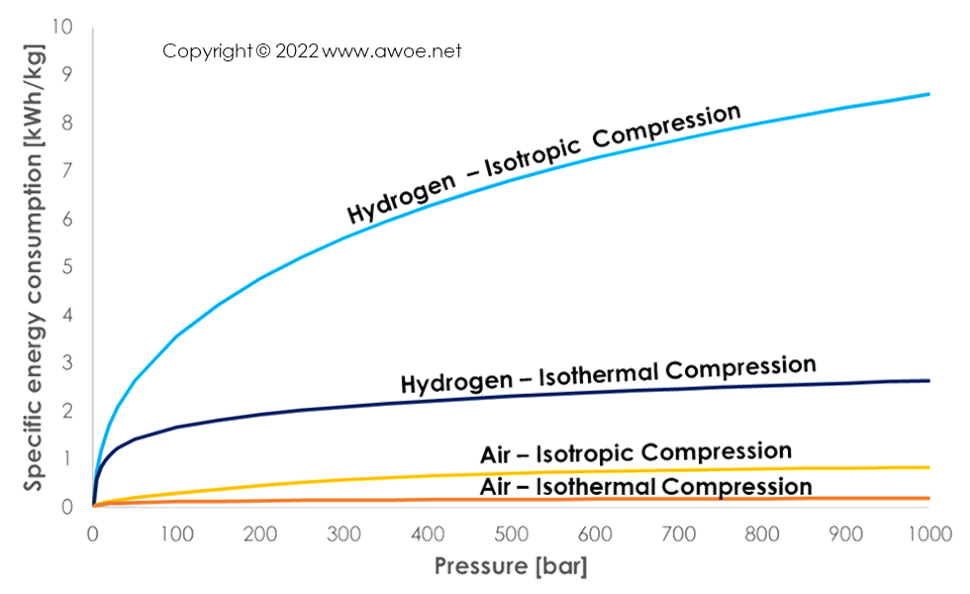
Comparison of specific energy consumption for hydrogen and air compression
Hydrogen has unique properties that lead to safety issues during compression and storage. While an ordinary gas cools down when expanding, hydrogen at any temperature above its inversion point (-80°C) heats up when expanding. The problem is that gas expands from compressor outlet to storage tank or in case of leakage. An ordinary gas would therefore be cooled and become less reactive, but hydrogen is becoming hotter and more reactive. In case of leak towards the ambient, a hot hydrogen/air mixture is created which can self-ignite if hydrogen concentration is above a few percents.
Mechanical compression
Mechanical compression uses some torque (directly or indirectly) to force hydrogen into a smaller volume, increasing its density and therefore pressure by minimising the temperature increase. A direct conversion of torque into H2 pressure implies a contact between hydrogen and the parts moved by the torque source. An indirect conversion relies on some intermediate step that isolates hydrogen from the torque source. The main objective of such an isolation is to avoid contamination of hydrogen by the lubrification of the torque source.
The list of direct converters includes:
- Reciprocating piston compressors, creating pressure by volume reduction
- Positive displacement rotary compressors, creating pressure by forcing flow into a dead-end volume
- Centrifugal compressors, creating pressure by converting induced velocity
The indirect compressors generally use a reciprocating piston as pressure source to operate the actual hydrogen compression device:
- Diaphragm compressors, using a flexible membranes to isolate hydrogen from the compressing piston
- Ionic compressors, using a liquid to isolate hydrogen from the compressing piston
Reciprocating piston compressors
Reciprocating piston compressors increase pressure by moving a piston within a closed chamber and therefore reducing the volume in-which the gas sits. The piston motion itself can be controlled in 2 different ways:
- Mechanically, through a crank-conrod mechanism
- Hydraulically, by forcing oil into the chamber acting at the back of the piston
The purely mechanical reciprocating piston compressors act like reciprocating piston engines, except that they absorb torque to release high pressure gases rather than burn high pressure gases to release some torque. The hydraulic devices have an external oil pump that can flow high pressure oil in and out of a control chamber acting on the piston opposite side to hydrogen.
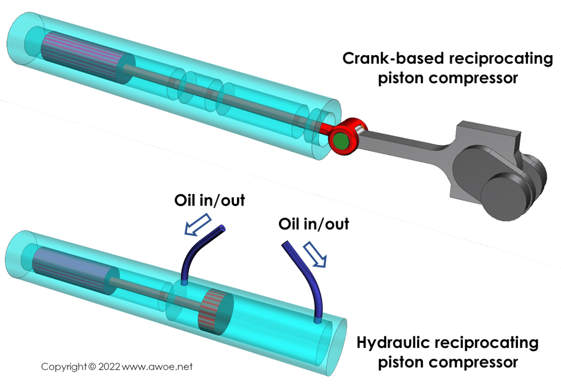
Types of reciprocating piston compressors
Whatever the method for piston motion control, the compression ratio per compression stage is limited to around 10 because of geometrical considerations in the compression chamber, mainly the minimum acceptable tolerance between the piston and the facing stationary wall.
Reaching pressures near 1000 bar with a gas supplied at 10 bar only requires 2 compression stages at a ratio of 10:1. Depending on flow demands, these 2 stages can either be done with a single compression unit or with 2 compression units in series. If a single compression unit is chosen, an intermediate tank is used to store the gas between first and second stages. In any case, an intercooler is used between stages to reduce hydrogen temperature both for safety and efficiency reasons.
Such compressors benefits from decades of experience at manufacturers and at end-users, so that they are extremely reliable with well-known service intervals and short-duration downtime at each service. They therefore offer long durability, long operating hours, very high pressure capabilities as well as high flow rate capabilities. However, isothermal efficiency is restricted to about 45%, including consumption by auxiliaries (energy consumption is at least 5.8 kWh/kg).
Reciprocating piston compressors can be oil-free when low pressures or moderate flow rates are targeted. By as soon as high pressure (> 350 bar) or large flow rate is required, part lubrification is mandated. This lubrication is detrimental to hydrogen purity, hence the use of "inserts" to isolate the hydrogen from any oil-based contaminants. Such "inserts" can be a diaphragm (see Diaphragm compressors below) or an ionic liquid (see Ionic compressor below).
Positive displacement rotary compressors
Positive displacement compressors use a pair of intrincate parts (gears, lobes, screws,...) with small tolerance between them to force the gas from inlet into a dead-end outlet tank where mass accumulation creates pressure. Tolerance between parts control leakage back to the inlet and becomes very challenging when pumping hydrogen because of its extremely low density and viscosity.
Centrifugal compressors
Centrifugal compressors transfer energy to the gas by forcing it into motion, the induced velocity being later converted into pressure by progressive increase of the piping cross-section. This is the method of choice to create high flow rates but it has a limited pressure ratio capability per compression stage (maximum 4-5). Accordingly, centrifugal compressors are widely used for pipeline applications but are not appropriate from high-pressure storage.
Diaphragm compressors
A simple way to isolate hydrogen from any lubrication residue is to implement a diaphragm (single or multiple layers) in-between the pressure source and the hydrogen feed. The pressure source acts on one side of the diaphragm deforming it and pushing it against the gas on the other side, essentially transmitting pressure.
The design of the transmission chamber and of the diaphragm is critical to maximise the pressure transmission while minimising the stress within the diaphragm to reach long operating hours. The cavity is concave with its outer shape guiding the diaphragm deformation.
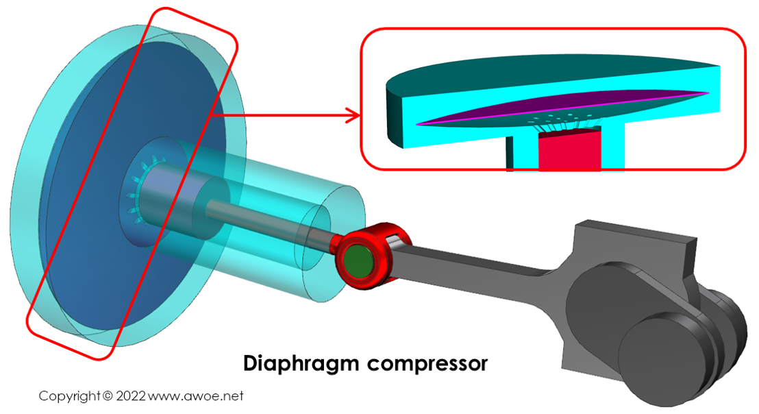
Schematics of a diaphragm compressor
Multiple methods for creating input pressure on the diaphragm are possible. Oil can be forced in and out of a chamber by a hydraulic pump or a crank-piston mechanism can create pressure on a transmitting fluid acting on the diaphragm.
Leaving some room for diaphragm deformation means an increase in dead volume compared to the direct compression with a piston and therefore a lower compression ratio. To compensate a lower pressure ratio at each stage, diaphragm compressors include more compression stages with cooling in-between each step. The added cooling events bring the compression path closer to an isothermal compression, therefore improving overall efficiency (up to 70% isothermal efficiency is claimed, i.e. an energy consumption of at least 3.7 kWh/kg).
Multi-layer diaphragms allow for varying mechanical properties or varying physico-chemical properties. A material with limited mechanical properties but not suffering from accelerated ageing when in contact with hydrogen might notably be used on the hydrogen side to protect another layer with good mechanical properties but a sensitivity to hydrogen. A third internal layer can be inserted to detect any leak from upper or lower layer, therefore ensuring the absence of both hydrogen leak and contamination for applications with mandated purity.
Ionic compressors
Ionic compressor are reciprocating piston compressors with a pair of liquids acting on the piston to optimise the efficiency of compression.
The piston motion is controlled by oil pressure on the side opposite to hydrogen. The absence of mechanical parts to move the piston and the absence of mechanical seals (piston rings) minimise friction, both improving efficiency and reducing heat rejection towards hydrogen. However, that oil pressure must be generated by a remote mechanical device with its own loses.
On the hydrogen side of the piston, an ionic liquid is located in-between the solid piston and gaseous hydrogen. Ionic liquids are selected because they have a non-measurable vapour pressure (essentially not vaporising and contaminating hydrogen), a very wide domain over which they remain liquid, and are not absorbing hydrogen. The ionic liquid protects the piston from hydrogen (no accelerated metal ageing) and the hydrogen from the piston (no contamination).
In addition to isolation, the ionic liquid can be used to increase the effective compression ratio of each stage. In a metal piston application, the distance between the piston and the facing stationary surface cannot come close to zero to avoid damages linked to metal part contact at speed. With a liquid being the effective piston, that distance can be further reduced as any excess liquid would leave the compression stage with hydrogen through the release valve. Because the ionic liquid and hydrogen are not miscible, this is not equivalent to contamination as a simple vortex flow would induce perfect gas/liquid separation.
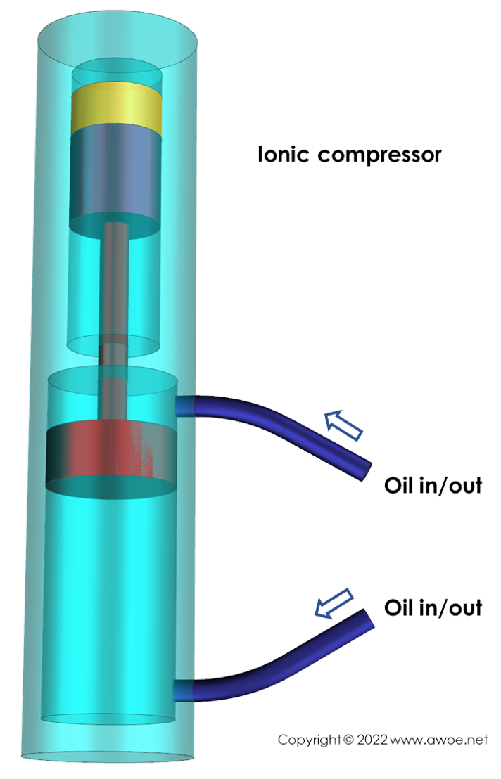
Schematics of a ionic compressor (yellow volume is the ionic fluid)
Ionic compressors (mainly developped by Linde) are today available for fuelling stations and deliver low to intermediate flow rates (up to 33.6 kg/h). Linde reports an electric consumption of 2.7 kWh/kg to compress H2 from 50 to 900 bar (1.2 kWh/kg required through an ideal isothermal compression) for the complete installation including all auxiliaries.
Non-mechanical compression
Non-mechanical compression methods aim at exploiting hydrogen properties to compress it without electricity conversion into mechanical power, thereby saving some energy and improving efficiency. The methods currently in development are mainly:
- Electrochemical compression
- Metal hydride
Electrochemical compression
Using proton exchange membrane, i.e. a membrane permeable only to H+ ions, it is possible to increase hydrogen pressure by dissociating it upstream the membrane and recomposing it on the other side. An external power source is required to drive the dissociation of H2 into H+ at the anode with a transfer of released electrodes e- to the cathode where H2 is formed again.
While each transfer through a membrane only leads to a moderate increase in pressure, a stack of membranes allow to reach up to 1000 bar. On-going research claim that efficiency could be as high as 70-80%.
This type of compressor is very compact and has no moving part, limiting the maintenance requirements. However, the progressive membrane degradation restricts the useful life well below that of a mechanical compression device.
Metal hydride
Metal hydride compressors rely on the properties of some metals that can release heat while absorbing hydrogen at low temperature to form hydrides. Once resulting hydrides are themselves heated, hydrogen is released at a higher pressure. The metal hydride can be heated with hot water or with an electric current in to order to trigger the hydrogen release.
This method can be used either as a pure compression device or as a storage device with low pressure feed and high pressure release, combining the compression and storage steps into a single unit.